Maintenance Hardware Insertion Machine Maintenance Schedule Maintenance Schedule
This maintenance schedule is applicable for
Warning!
standard machine shop operating conditions. DO NOT lubricate the Upper Tool
When operating under severe conditions such as
Holderwith any lubricant other than a
heavy dust and dirt, increase the schedule to
(white).** Other products may inter-fere with the Safety System. Component Maintenance Schedule
procedures using “Testing theSafety System”
(See warning
** Note: Lithium GreaseEach Haeger machine is shipped with a tube of
Lubriplate 630-AA, produced by Fiske BrothersRefining Company. In Europe, Fiske Brothers isrepresented by Total Deutschland GmbH.
* Equivalent hydraulic oils may be used. It is the machine owner’sresponsibility to determine which hydraulic oils in their area are equivalentto Mobil AW-32. Maintenance Hardware Insertion Machine
Problem Possible outages Solution/ Checks1) Machine will not turn on
1.1.1) Rotate Red stop button clockwise. This will cause the stop button to unlatchand pop out for the start mode.
1.2.1) Turn disconnect to the on position
1.2.2) Open the cabinet and insure thedisconnect switch attachment bar is stillconnected to the switch inside the cabinet.
1.2.3) Inspect the condition of thedisconnect switch handle for any damageand alignment to the attachment bar.
1.3.1) Inspect to insure machine isplugged in to the correct power supply.
1.3.2 ) using a meter check the volts onthe 3 phase disconnect switch inside theelectrical cabinet to insure it matches theidentification plate on the back of themachine.
1.4.1) Reset circuit breaker. If circuitbreaker trips again go to next step.
1.4.2) Using a volt meter, insure the powercoming into the machine is correct. Youcan look at the identification plate on theback of the machine for the correct voltrequirements.
1.4.3) There is a fault with either themotor or the safety board. To determinewhich is at fault, disconnect the threewires from the circuit breaker going to themotor and restore power. If circuit breakerstill trips then go to next step. If circuitbreaker does not trip, inspect motor wiringfor damage and check electricalconnections at motor including groundwire connection. If all wiring is ok andconnections are tight change out motor.
1.4.4) Check transformer for looseconnections. Maintenance Hardware Insertion Machine
Problem Possible outages Solution/ Checks
1.4.5) Check volts on discharge side oftransformer. If not correct change outtransformer. If correct go to next step. Should be 19 VAC
1.4.6) Check VDC between terminals T-14(+) and T-74 (-) and they should read24VDC. If not correct change out Dirty24VDC power supply. If correct go to nextstep.
1.4.7) Check VDC between Terminals T-42 (+) and T-2 (-) and they should read24VDC. If not correct cha2.3.1) Check tosee if the green start push button lights upwhen depressed. If the push button lightsup but motor will not start, manuallydepress the button on the Mag Starter. Ifthe motor starts then go to next step. If themotor does not start replace Mag Starter.
1.4.8) Call Haeger for more technicalhelp at 1-209-848-4000
2) Machine turns on but motor 2.1) Overload relay tripped
relay trips again check to insure thecorrect volts are being supplied to themachine.
2.1.2) Check wires going to the motor forany signs of damage or loose connections.
2.1.3) Inspect connections at motor fortightness and inspect ground terminal fortightness. If ok change out motor. If not okfix problem and retest.
2.2.1) Check for voltage at overload relay. If no voltage present on discharge side,change out overload relay. If voltage ispresent go to next step.
2.2.2) Check connections at motor fortightness and check ground screw fortightness. If ok , check for voltage atmotor. If ok, change out motor. If not okinspect wiring for damage. Maintenance Hardware Insertion Machine
Problem Possible outages Solution/ Checks
2.3.1) Check to see if the green start pushbutton lights up when depressed. If thepush button lights up but motor will notstart, manually depress the button on theMag Starter. If the motor starts then go tonext step. If the motor does not startreplace Mag Starter.
2.3.3) Check for 24vdc at terminal 14 onthe Mag Starter. If there is no voltage,check F6 fuse for damage. If there is 24vdc go to next step.
2.3.4) Check for 24vdc at terminal 3 onthe Green start push button. If there is novoltage check wire from terminal 14 on theMag starter to terminal 3 on the green startpush button for damage. If there is voltagego to next step.
2.3.5) Check for 24vdc at terminal 4 onthe green start push button when it isdepressed. If there is no voltage, changeout start push button. If there is voltagepresent then check the wire condition fromterminal number 4 on the green pushbutton to terminal 13 on the Mag starterfor damage. Also check the P.C fan motorfor continuity. The fan motor connects tothe start push button on terminals X1positive and X2 negative. If these checkout please go to step 2.4
Maintenance Hardware Insertion Machine
Problem Possible outages Solution/ Checks
2.4.1) Remove wire T-61 from the safetyrelay board and ensure the wire is nottouching anything. It will have 24vdcsupplied to the wire. Try and start machinewith T-61 disconnected. If machine startsup we need to check all item on that circuitto find what is shorted, it the machine doesnot start up go to step 2.5 Power supplyshorted. Reconnect wire T-61 and thenremove the following wires one at a timeand check if machine starts with each wireremoved. If the machine starts with one ofthese wires disconnected, troubleshoot thatcircuit to find the short. T86, T85, T62,T63, T64, T65, T66, T67. Also pull relaysR1, R2, R3, R6, K6 AND K9. If none ofthe wires or relays while disconnectedallow the machine to start up, then changeout the safety relay board.
2.5.1) Check to ensure 24vdc is coming outof power supply. While the meter is stillhooked up, depress the start button and ifvoltage drops low ( 1-7vdc ) change outpower supply. Maintenance Hardware Insertion Machine
Problem Possible outages Solution/ Checks
This next section deals with fuses blowing. Typically the problem is with a component shorted to ground. The trouble shooting method we will be using involves disconnecting wires to isolate components orelectrical legs. Please follow the procedure outlines and do not skip steps. Caution needs to be taken becausesome wiring may be HOT. Ensure you have extra fuses and they are the correct AMP rating as the onecurrently in use.
the P.C board. Restore power and check ifF1 fuse blows. If it does then change outthe Clean 24vdc power supply unit. If itdoes not blow, go to next step.
3.1.2) Reconnect wire T-4 and restorepower. If F1 fuse blows, then turn offpower and reconnect T-41 and go to 3.2.1. If F1 fuse does not blow then reconnectWire T-4 and go to 3.3.1
Maintenance Hardware Insertion Machine
Problem Possible outages Solution/ Checks
3.2.1) To isolate which leg on the E-Stop is
shorted you will need to pull the followingFuses. F3, F2 and F6. Turn power back onto the machine and if F1 Fuse blows,Change out E-stop. If F1 does not blow,Replace Fuse F3. Turn power back on andif F1 Blows then follow the procedure forF3 fuse blowing. If F1 does not blowreplace F2 Fuse. If F1 fuse blows thenfollow the procedure for F2 fuse blowing. Iffuse does not blow then replace fuse F6. IfF1 fuse blows then follow the procedure forF6 Fuse Blowing. If none of these solvesthe problem to a root cause, then changeout P.C Board.
3.3) PLC or Expansion Module 3.3.1) Unplug both PLC and Expansionshorted.
Module power plugs on the bottom of theunits and turn on power. If Fuse F1 blowsthen check wiring to both units for shortsto ground. If fuse does not blow, thenreconnect the PLC power plug and turnmachine back on. If fuse F1 blows, changeout the PLC. If the F1 fuse does not blowthen reconnect the power plug for theExpansion Module. If the F1 Fuse Blows,change out the Expansion Module.
4.1.1) Check for a short from terminals T-33 and T-25. If no short found go to nextstep. If short is found, replace fan.
4.2.1) Unplug touch screen power cord andcheck for a short. If a short is foundreplace the touch screen. If no short isfound go to next step.
4.3.1) Check the stop switch for a short. Ifa short is found, replace the stop switch. Ifno short is found, call Haeger at 1-209-848-4000
Maintenance Hardware Insertion Machine
Problem Possible outages Solution/ Checks5) F3 fuse blows
5.1.1) Check wiring from the footswitch tothe cabinet for damage. If wiring appearsto be ok go to next step. If not ok, repair orreplace wiring.
5.1.2) Remove wire from terminal T-50 and replace fuse. Turn power back onand see if fuse blows. If fuse still blows goto 5.2. If fuse does not blow, change out thefootswitch and reconnect wire to T-50
5.2.1) Check wiring on the back of the keyswitch for tightness or damage. If wiringappears to be ok go to next step. If problemis found, repair as needed.
5.2.2) Remove wires from terminals T-49and T-67 and replace fuse. Turn powerback on and if the fuse blows then go to5.3. If fuse does not blow then replace keyswitch and reconnect T-49 and T-67 wires.
5.3.1) Pull relays R1 and R2 and inspectthe pins on the back for damage. If damageto the pins are found replace the relays. Ifno damage is found go to 5.4.
shorted we will remove the wire terminals
T-48 (analog module), T-45 ( CET ), andT-46 (pressure transducer). Restore powerand if F1 fuse blows replace or inspect E-stop wiring for shorted to frame. If fusedoes not blow, reconnect Wire T-46 andTurn on power. If F1 fuse blows change outthe pressure transducer. If Fuse F1 does notblow reconnect wire T-45. If F1 fuse blowsthen change out the CET module. If FuseF1 does not blow then reconnect wire T-48. If F1 fuse blows, unplug the mainconnector on the front of the analogmodule and turn power back on. If Fuse F1still blows then change out the analogmodule. If F1 fuse does not blow, turn offpower and check wiring on connector forany shorts to ground. Maintenance Hardware Insertion Machine
Problem Possible outages Solution/ Checks6) F4 Fuse blows
6.1.1) Unplug all MAS connectors from the back ofthe machine at the quick disconnects. Insure youreconnect them to the proper location to avoid start upproblems. Replace fuse and turn power on. If fuse stillblows go to 5.2. If fuse does not blow then check for ashort in one of the MAS and repair as needed.
8.1.1) To isolate which leg is causing the problem we
will first pull the following relays from the board. R1,
difficult to troubleshoot. We will R2, R3, R6, K6, K9 AND K5. Turn on power and see ifguide you through the process
F6 fuse blows. If F6 fuse blows then go to 8.2 If F6 fuse
8.2.1) To isolate the components to find the cause of the
short please follow closely. Replace all relays from step
control Cabinet, Non conductive 8.1.1 Next remove wires T-63, T-60, T-86, T-62, T-67&Key Switch, Safety Switch, or
T-61 Turn on power and if F6 fuse blows then
reconnect all the wires back and Change out mag
starter. If fuse does not blow then reconnect T-15 andturn power back on. If fuse F6 blows, change out greenstart push button. If the fuse does not blow, reconnectwire T-62. If F6 Fuse blows, disconnect all MAS plugsat back of machine and reconnect them one at a timewith turning the power on and off after each one isconnected to find the one causing the outage. If the F6does not blow after wire T-62 is connected, reconectwire T-67. If fuse F6 blows, change out the conductivekey switch. If F6 Fuse does not blow, reconnect wire T-86. If F6 fuse blows, change out the buzzer inside theP.C console. If F6 fuse does not blow, Reconnect wiresT-60 and T-63. If F6 Fuse blows, change out the stepperDriver Board. Maintenance Hardware Insertion Machine
Problem Possible outages Solution/ Checks
8.3.1) Pull Relays R1, R2, R3, K5, K6, K9. Insert one really at a time and turn onpower to see if the fuse F6 blows. Until youfind the relay or path causing the short. Then Change out they relay.
9.1.1) Check to ensure that wire T-3 isconnected to the grounding strap on thesafety switch.
10.1.1) Pull fuse F-10 and turn on power. If F9 fuse blows, change out P.C Board orreplace the 6 volt rectifier on the board.
12.1) 24 vdc clean power supply 12.1.1) Change out 24vdc clean powershorted
13.1.1) With Power off Disconnect WiresT-34 and T-33. Turn on power and If F22Fuse Still Blows Call Haeger at 1-800-848-4000. If fuse does not blow, turn off powerand reconnect T-33. Repeat process andturn on power. If Fuse F22 Blows, changeout the fan in the electrical cabinet. If fuseF22 does not blow, turn off power andreconnect T-34. Turn on power and if fuseblows check e-stop for wiring damage orshorts to ground.
14.1.1) Change out Proportional Amplifier.
condition of check valve. If damagedreplace housing.
16.1.1) Ensure machine is and motor isturning.
16.2.1) Ensure ram is at full top of stroke. Maintenance Hardware Insertion Machine
Problem Possible outages Solution/ Checks
16.2.2) Check top of stroke setting underthe administration screen for proper set up.
16.3.1) Check to ensure yellow string isconnected to top of ram and that there is noslack. If slack is present check alignmentof CET to top of ram or change out CETunit.
16.4) Top of Stroke setpointincorrect.
16.4.1) Check the Top Of Stroke set pointon the Change PLC Values screen. Shouldbe atleast 10 numbers below the currentvalue reading wiht the ram at full up
16.5.1) Check the diagnostic screen underinputs or look at PLC lights inside cabinet,and check for X4 to be checked or lightedwhen the down foot pedal is pressed. If thelight does not come on then check for24vdc at terminal T-50 to ground. If poweris present then change out foot switch. Ifpower is not present then check Fuse F3 for
16.6.1) Check relays K6 and K9 for proper
16.7) Check to see if R3 or R6 areactivated. If these are activated and theupper tool is not touching lower tool, thenyou must look for a short from the Ram ToFrame. Typically this will happen becauseof a loose guard or one that has some metalshowing at or near the top portion of theram. Note The ram must be completely
isolated form the frame except for tooling
16.8.1) Ensure there are no hydraulic leaksat hose connections and fittings. Alsocheck to ensure there is enough hydraulicfluid in the tank. Maintenance Hardware Insertion Machine
Problem Possible outages Solution/ Checks
16.9.1) Check to see if the light on thedown solenoid is coming on when thedown footswitch is depressed. If the light iscoming on, manually activate the downsolenoid and see if the ram comes down. Ifthe ram comes down then change out the4way valve. If the ram does not come downcheck for other hydraulic problems.
17.1.1) Check the Top Of Stroke set point
on the Change PLC Values screen. Shouldbe atleast 10 numbers below the currentvalue reading wiht the ram at full upposition.
17.2.1) Check for output Y9 on the PLC tosee if it is on. If not check to see if X4 onthe PLC is on when stepping on the uppedal at the foot switch. If X4 does notcome on check for a shorted foot switch. IfY9 on the PLC does come on then go to
17.4.1) Check the PLC input X5 is comingon when the up pedal is depressed.
17.5) 4 way up solenoid valvenot working.
17.5.1) Visually check the up solenoidvalve on the 4way to see if it lights upwhen the up pedal is pressed. If it doeslight up the manually depress the 4wayvalve. If the ram goes up, change out the 4way valve. If there is no light on the up
solenoid, verify wiring and power going toup solenoid.
17.6.1 ) Verify there is power at T-20 (24vdc) and then check for power at
Solenoid valve. If no power at valve butthere is power at T-20, check for a brokenor loose wire.
18.1.1) Check to ensure there is enoughfasteners in the MAS. Maintenance Hardware Insertion Machine
Problem Possible outages Solution/ Checks
the singulation module to ensure that there
18.3.1) Check to see if the green light is onthe MAS. This indicates power is on.
18.4.1) Pull the fuse on the front of theMAS unit and check for damage.
18.6) Air blast is wide open not 18.6.1) Check to ensure the air blast is notallowing enough air to feed
full open not allowing enough air to actuate
the air cylinder on the singulation module.
cylinder to ensure there is no binding.
18.8.1) Check to ensure the feed hose is not
kinked and there are no fasteners jammedin hose.
18.9 ) Air Timer Is turned down 18.9.1) Check the Air timer and the airto zero.
blast settings to ensure they are properly setto allow enough time to get fastener downto upper tool.
turned 180deg from the singulation moduleto the upper tool holder.
modules are installed for the fastener youare running.
20) Ram comes down and taps material while in the conductive mode for the material you are running. and then returns up. No
20.2) Lower tooling or material 20.2.1) Check the condition of the loweris dirty.
tooling and the material. If the material isdirty this will not allow tooling contact totake place. Maintenance Hardware Insertion Machine
Problem Possible outages Solution/ Checks
continuity springs and pins. Also check toensure the upper tooling is not binding onthe shaft.
20.4.1) Check the condition of the safetyswitch. Bring the ram down to mid strokeand lift up on the upper tool. If the ramdoes not return up then inspect the safetyswitch system for damage.
20.5.1) Check the pressure transducer for
proper operation by turning off the machineand checking the pressure reading on theadministration screen. If pressure showszero start machine and take reading. Ifpressure rises above 30psi turn off machineand inspect the hydraulic system.
20.5.2) Check the condition of theproportional amplifier.
20.7) Relays R3 or R 6 burnt or 20.7.1) Check to see if relays are cycling. not working.
Check contacts for burnt conditions. If thecontacts appear burnt, change out relay.
21) Ram Comes Down, buildspressure, but will not return up. 21.1) Machine in set up mode.
21.1.1) Check run screen to ensure it is notin set up mode. This can also be determinedby a yellow run screen.
the administration/ change plc values. Thereading should be no more than 30 at idle. Also check the set point to ensure it is at 60to 90. If the set point is not correct, adjustto 90. If there is no pressure being shown atidle, Check the wiring and plug going tothe pressure transducer for damage or looseconnections.
21.3.1) While watching the pressure screen,operate machine and verify the pressuregoes above the set point. Example: Ifpressure only reaches 60 and set point is at90, adjust set point to 55. Maintenance Hardware Insertion Machine
Problem Possible outages Solution/ Checks
22.1) TPS sensitivity set to low. 22.1.1) Reset TPS using the part and
22.2.1) On older machines - set the TPSusing min pressure. On high speedmachines it does not matter what force isselected.
22.3) Continuity pins and spring 22.3.1) Check the springs and pins in theworn causing incorrect set
upper tool holder for damage or collapsed
23.1) Numerical overflow error much information had been entered on any
given line or too many characters. Examplewould be TPS setting containing astrics. Look for this occurrence on all informationwindows in the run screen, admin screen,password screen, program screens.
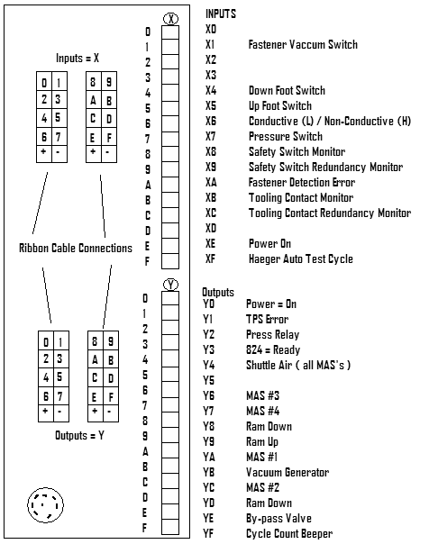
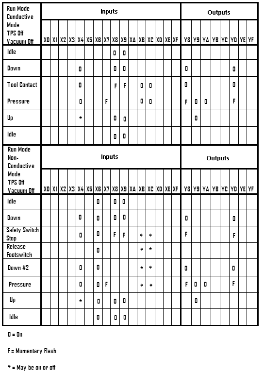
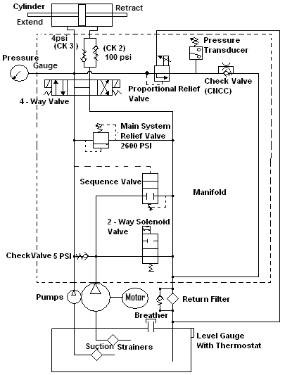
23.1.2) If you can not find the problem,reload the software and this will resetdefault values. Maintenance Hardware Insertion Machine Relay Table Maintenance Hardware Insertion Machine I/O Table Maintenance Hydraulic Schematic Hardware Insertion Machine Wiring Diagram Maintenance Hardware Insertion Machine Problems
Problems?• Have you worked your way through the
• You still haven’t resolved the problem?
Call your HaegerDistributor!Their telephone number is on the Basic DataSheet in the Introduction Section of this manual. To save time, please be prepared to give your area Haeger Distributor the following information:
1. Your name.
2. Your company’s name, location and telephone number.
3. The Model Number of your Haeger
4. The Serial Number of your Haeger
5. A very detailed description of the prob-
6. What steps you have already taken to
7. How the machine responded to each of the Maintenance Hardware Insertion Machine
North Carolina Swimming - For Office Use Only License 2011 NC ASC/SMAC Dual - 10/8/2011 Girls 8 & Under 25 Yard Freestyle Girls 9-10 200 Yard Freestyle Relay Finals Time Finals Time Girls 8 & Under 25 Yard Backstroke Finals Time Girls 10 & Under 50 Yard Freestyle Girls 8 & Under 25 Yard Breaststroke Finals Time Finals Time Girls 8 & Under 2
After School Program FAQ’s & Answers 1. How do I contact the After School Program? a. Please contact Yasmin Ulloa at 732-329-1150 x203. You may also call our main number, then dial “0” for the Welcome Center. The operator will page someone from the program. You may also leave a message on x221. 2. Is the program licensed? a. Yes. Our program is licensed by the NJ D
 Maintenance
 Maintenance
 Maintenance
 Maintenance
 Maintenance
 Maintenance
 Maintenance
 Maintenance
 Maintenance
 Maintenance
 Maintenance
 Maintenance
 Maintenance
 Maintenance
 Maintenance
 Maintenance
 Maintenance
 Maintenance
 Maintenance
 Maintenance